Fiber Reinforced Polymer for Reinforced Concrete Structures, ACI SP-188, pp. 1131-1144, 1999. 10
@
BOND SPLITTING BEHAVIOR OF CONTINUOUS FIBER REINFORCED CONCRETE MEMBERS
by Takahiro Sakai, Toshiyuki Kanakubo, Keisuke Yonemaru and Hiroshi Fukuyama
@
Takahiro Sakai is a graduate student of doctoral program of University of Tsukuba, Japan. Toshiyuki Kanakubo, Dr.E. is an Assistant Professor of Institute of Engineering Mechanics, University of Tsukuba, Japan. Keisuke Yonemaru, ME, is a Research Engineer of Institute of Technology, Shimizu Corporation, Japan Hiroshi Fukuyama, Dr.E. is a Senior Research Engineer of Building Research Institute, Ministry of Construction, Japan
Synopsis: For the purpose of investigating the bond splitting behavior of continuous fiber reinforced concrete (CFRC) members, two series of investigations were conducted. The first series was performed in order to obtain the local bond behavior in the case of splitting failure of the concrete cover for members with or without lateral reinforcements. For specimens without lateral reinforcement, test results show that the bond splitting strength is not influenced by the Young's modulus of the reinforcement and that it is approximately proportional to the thickness of the cover concrete. On the other hand, for specimens with lateral reinforcement, the local bond splitting strength is greater than the case where there is no lateral reinforcement. The strength is also independent of the mechanical property of the lateral reinforcement and is determined solely by the thickness of concrete cover. For both types, a new relationship between the bond stress (Ρ) and the slip of reinforcements (s) is proposed.
The second series was an analytical study to investigate the average bond behavior of CFRC members, which had several bond lengths and Young's moduli. Analytical results show that in the case of large bond lengths, the analytical bond splitting strength is inversely proportional to the bond length, and is clearly influenced by the Young's modulus of the reinforcement. It is considered that continuous bond failure from the loaded end causes a remarkable decrease in the bond strength especially for large bond lengths and low Young's moduli.
@
INTRODUCTION
@
In recent years, research involving the use of Fiber Reinforced Plastic Reinforcement (FRPR) as the main reinforcement in concrete is being conducted frequently, especially, bond splitting experimental tests. Experimental results on the cantilever specimens having a bond length of 23 times the main bar diameter show that the length of the stressed portion on the FRPR bar is about 10 times the main bar diameter (1). It is also considered that a low Youngfs modulus causes the bond splitting failure from the loaded end to be of the continuous failure type and that the length of the bond stress acting could be influenced by Youngfs modulus of the reinforcement. Youngfs modulus of FRPR could be varied by the material, surface configuration and so on.
To investigate the relationship between bond splitting strength and Youngfs modulus of reinforcement or bond length of the specimen, the bond splitting test was conducted with FRPR as a main bar.
@
BOND SPLITTING STRENGTH ACCORDING TO TEPFERS
@
Tepfers (2) presented the bond splitting strength by modeling the stress condition of the surrounding concrete around the loaded main bar to the internal stresses present inside a cylinder (Fig. 1). The tensile stress, ΠΖ , acting at a radius , r , from the main bar in a hollow cylinder with an inner radius , ri , and outer radius, ru , having an inner stress, Π , is given by eq.[1] according to Timoshenko (3).
If it is assumed that the bond splitting occurs when the tensile stress,ΠΖ , equals the splitting strength of the concrete,Πt , at a distance equal to the inner radius, ri , the internal stress,Π, can be represented in eq.[2]. As shown in Fig. 1, the resulting stresses made when the main bar pushes against the surrounding concrete is composed of the lateral component,Πs , and the bond stress along the direction of the main bar,Ρb , and whose relation is given in eq.[3]. Also, assuming equilibrium of the compressive forces acting inside cracked inner portion of the cylinder, the relationship between Πs and Π can be represented in eq.[4]. Thus, by substituting eq.[3] and eq.[4] into eq.[2], the bond stress is given by eq.[5]. By differentiating Ρb by ri, the maximum value of the bond stress is derived as given in eq.[6].

 Fig. 1 Internal stress and bond stress

 [2]
[2]
![]()

![]()
@
EXPERIMENTAL TEST
@
Test Program
@
To obtain the local bond behavior in the case of splitting failure of the cover concrete, an experimental test was conducted.
As shown in Fig. 2, specimens with a bond length of four times the diameter of the reinforcement were tested. Slits on four or two sides of each of the specimens were designed in order to fail by concrete splitting along the slits. Thickness of the cover concrete (C) is varied by length of the slit. Two types of specimens were designed. One is for specimen without lateral reinforcement (hereafter called Type A), and the other is for specimen with lateral reinforcement (called Type B). Type B specimens, one main bar was positioned at the center of the specimen and also, a single bent bar was arranged in a manner representative of the bar arrangement in a structural member. The portion of the lateral reinforcement lying along the loading direction is unbonded.
A monotonic tensile load was applied until failure occurred. In Type B specimens, proportional tensile load to main bar load was applied by two oil jacks. The measured items were the tensile load and the slip of the free end of the main bar.
@


Type A (without lateral bar) Type B (with lateral bar) Fig. 2 Outline of the specimen
In Type A specimens, different types of reinforcement were used as main bars, namely, ordinary steel (diameters of 13, 16, 19 and 25mm), carbon and glass (diameter of 16mm). For the carbon bar, two types were used, wherein either carbon or glass were coiled around the surface of the carbon bar. On the other hand, in Type B specimens, different types of reinforcement were for the lateral bars, ordinary steel (diameters of 4, 6, and 8mm), carbon, glass (diameter of 6mm) and aramid (diameter of 6mm). Mechanical properties for each of the reinforcements are shown in Table 1.
In Type A specimens, design compressive strength of 36MPa concrete, and in Type B specimens, design compressive strength of 20, 30 and 45MPa concrete were cast. The material test results are shown in Table 2.
Table 1 Mechanical properties of the reinforcement|
Mate -rial |
Surface configuration |
Name |
Cross-sectional area Ab (mm2) |
Diameter db (mm) |
Perimeter Σ b(mm) |
Youngfs modulus Eb (GPa) |
Speci men |
|
Steel |
Deformed |
D4 |
14.1 |
4.2 |
13.3 |
191.0 |
TypeB |
|
15.7 |
4.47 |
14.05 |
181.5 |
||||
|
D6 |
30.4 |
6.2 |
19.6 |
176.0 |
|||
|
31.3 |
6.31 |
19.83 |
189.9 |
||||
|
D8 |
59.2 |
8.7 |
27.3 |
185.0 |
|||
|
45.6 |
7.62 |
23.94 |
186.9 |
||||
|
SD13 |
123.1 |
12.5 |
39.3 |
182.4 |
TypeA |
||
|
SD16 |
192.0 |
15.6 |
49.1 |
185.3 |
TypeA,B |
||
|
SD19 |
277.2 |
18.8 |
59.0 |
188.2 |
TypeA |
||
|
SD25 |
499.6 |
25.2 |
79.2 |
197.2 |
|||
|
Carbon |
Carbon spiral |
CS16 |
18.4 |
57.8 |
265.9 |
197.1 |
TypeA |
|
Glass spiral |
CS16G |
18.4 |
57.8 |
266.3 |
75.3 |
||
|
Straight |
C6 |
33.8 |
6.6 |
20.6 |
60.4 |
TypeB |
|
|
Glass |
glass spiral |
GS16 |
19.0 |
59.8 |
284.2 |
30.4 |
TypeA |
|
Straight |
G6 |
32.3 |
6.4 |
20.2 |
34.4 |
TypeB |
|
|
Aramid |
Straight |
A6 |
50.7 |
8.0 |
25.2 |
36.1 |
@
Table 2 Mechanical properties of the concrete|
Compressive strength Π B(MPa) |
Splitting strength Π t(MPa) |
Youngfs modulus Ec (GPa) |
Specimen |
|
|
36.4 |
2.83 |
24.0 |
SD13,fiber |
TypeA |
|
34.3 |
2.36 |
24.6 |
SD16,19,25 |
|
|
20.1 |
1.97 |
22.9 |
TypeB |
|
|
29.3 |
2.32 |
24.2 |
||
|
47.2 |
3.17 |
29.2 |
||
Test Results
@
Test results show that almost all the specimens failed by concrete splitting toward the slits (Photo 1). The maximum bond stress was derived by dividing the maximum load by the surface area of main bar.


Type A@@@@@@@@@ Type B
Photo 1 Typical failure type
Influence of the parameters on the bond behavior in case of no lateral bar : For this experiment, considering the type of reinforcement used, focus is made in the value of their Youngfs moduli. Therefore, a relationship between different values of the Youngfs modulus and the resulting bond splitting behavior is investigated as shown in Fig. 3. For this case, the values of the bond strength and slip are determined. The bond splitting strength is derived by the maximum bond stress divided by splitting strength of concrete. Fig. 3 shows that both bond strength and load end slip are not influenced by the variation of the Youngfs modulus of the reinforcement.

In investigating the influence of the thickness of the cover concrete, a relationship between ru/db (=C/db+0.5) and bond splitting strength is shown in Fig. 4 using a straight line plot derived from regression analysis. In the figure, the specimens are classified into the two types of the reinforcement, steel and fiber. Results show that the bond splitting strength is proportional to ru/db as could be shown in eq.[6], in spite of type of reinforcement. The determination of the value of cotΏ was done by using eq.[6] with the experimental results. The average calculated cotΏ for all specimens was 1.47, whereΏ was 34 degrees.

Influence of the parameters on the bond behavior with lateral bar : Fig. 5 shows the relationship between the Youngfs modulus and cross-sectional area of the lateral reinforcement and the bond splitting strength. Marks were changed for each type of lateral reinforcement. From both figures, it is observed that there is no clear trend showing that the influence given by the difference in the types of lateral reinforcement is negligible. Fig. 6 shows

 Fig. 5 Influence of the Youngfs modulus and sectional area
of the lateral reinforcements

the relationship between the concrete cover and the bond splitting strength. The value of eq.[6] (Ώ:34 degrees) is represented by the straight line. the bond splitting strength tends to increase as concrete cover increases. And the experimented values are greater than the calculated value. However, the amount of increase is not so large that, the difference in the types of lateral reinforcement and concrete cover is not so emphasized.
@
RELATIONSHIP BETWEEN THE BOND STRESS AND THE SLIP OF THE REINFORCEMENT
@
Basic Equation of the Slip of the Reinforcement in Bond behavior
@
Consider an infinitesimal elementx at arbitrary position of the main reinforcement, slip of the reinforcements, tensile force of the reinforcement P, tensile stressΠ, strain of the reinforcementΓ, and bond stressΡb to be determined. These parameters could have the following relationships.
![]()
![]()
where, Σb : perimeter of the reinforcement
ab : cross-sectional area of the reinforcement
Eb : Young`s modulus of the reinforcement
By using eq.[7]`eq.[10], the following eq.[11] and eq.[12] could be presented.
![]()
@
Relationship between the Slip of the Reinforcement
@
If some relationship between the inner radius, ri and the slip, s could be derived, Ρb can be shown as a function of s by eq.[5]. In investigating the relationship between ri and s, ri was determined by computer calculation with the substitution of the experimental bond stress in eq.[5]. A typical example of the relation between the calculated ri and loaded end slip s is shown in Fig. 7 (specimens using steel bars). This shows that ri is almost proportional to loaded end slip. To determine the proportionality constant, a relationship between the constant and the diameter of the reinforcement is needed and is as shown in Fig. 8. From which, eq.[13] is derived, where ΐ is 10.2. By substituting eq.[13] into eq.[5], the bond stressΡb could be represented in eq.[14].
![]()


and the load end slip @ proportionality constantΐ
@
Construction of a Model for the case with Lateral Reinforcement
@
Eq.[14] shows the relationship between the bond stress and loaded end slip of the case without lateral reinforcement. And Fig. 9 shows a example of the relationship between the bond stress and loaded end slip obtained using this experimental test for the case with lateral reinforcement, as well as the relationship between the bond stress and loaded end slip obtained by eq.[14]. To construct a model for the case with lateral reinforcement, emphasis is given to the increase in the amount of the bond strength Ρinc as represented by the shaded portion in the figure. The increase in the amount of the bond stress is defined as the difference between the experimental results using specimens with lateral reinforcement and theoretical results using eq.[14].

The left graph of Fig. 10 shows the example of the relationship between the increment of bond stress and loaded end slip defined in the previous paragraph. Here, the model of the relationship between the bond stress and loaded end slip is defined by two straight lines as shown in the right graph. The first line is the straight line increase from the datum point to the loaded end slip that rI becomes ru (rI = ru), and takes the maximum valueΡincmax that is equal to the concrete cover (ru)
Fig. 11 shows the relation between values of slope, k1 and k2, and lateral reinforcement ratio. Both values are standardized by concrete splitting strength. As shown in the figures, the value of first slope k1 is almost constant, and the value of second slope k2 is inversely proportional to lateral reinforcement ratio.
 @
@
 Fig. 10 The increase of bond stress and its model

 Fig. 11 Relation between values of slope and lateral reinforcement ratio
@
ANALYSIS FOR AVERAGE BOND BEHAVIOR
@
The Method of Analysis
@
The following step-by-step procedure is presented to obtain the average bond behavior such as acting in actual members using constructed bond stress - slip model. First, consider an its infinitesimal elementx at arbitrary position of the main reinforcement, and at free end, the amount of slip si-1 (= free end slip s0) and the tensile force of the reinforcement Pi-1 (=0) is determined. Second, for each element, determine the bond stress using the model. And since x could be considered as very small, the bond stress could be assumed as constant. The difference in the tensile force Pi and the amount of slip si at the infinitesimal element could be given by eqs.[15] and [16]. Lastly, the amount of slip at the other end of the infinitesimal element si and the tensile force of the reinforcement Pi could be represented by eqs.[17] and [18]. These procedure is conducted iteratively. Also, the determination of the average bond stress by dividing the calculated Pi at the loaded end with the perimeter of the main reinforcement and the total bond length is possible.
![]()
![]()
@
The Comparison between Analytical Results and Experimental Results
@
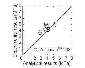
The analytical data adopted for the verification were the specimens having lateral reinforcement, and failed by the side splitting type in Yonemarufs research (4) as shown in Table 3. Fig. 12 shows the comparison between the experimental results and analytical results of the bond splitting strength. In this figure, the analytical results matches favorably with the past experimental results, and good conformity is noticed in the case of long bond lengths.
Table 3 The data used for the verification|
Ref. |
Number of data |
Member Width (cm) |
Main bar |
Lateral bar |
Concrete strength (MPa) |
Bond length (cm) |
Lateral bar ratio pw(%) |
|
Yon-emaru et al |
38 |
20 |
CFRP Σ6GFRP Σ13C128S K128S D13 |
CFRP Σ6,8GFRP Σ6,8C32,64 K32,64 U5.1 |
33.04 33.92 34.31 |
30 |
0.40 0.78 0.81 1.19 |

@
Influence of the Bond Length to the Bond Strength
@
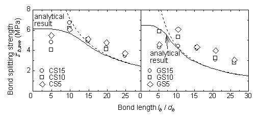
The influence on the bond splitting strength by bond length is given in Fig. 13. The analysis was conducted using two types of specimens, namely, carbon and glass as shown in the left and right graphs, respectively. The horizontal axis shows the bond length (divided by diameter of reinforcement, lb/db). In this graph, the analytical result is shown as the solid line, and the dotted line shows the inversely proportional line. Analytical results show that in the case of short bond lengths, the analytical bond splitting strength is given by the maximum local bond stress, while in the case of large bond lengths (larger than about 15 times of diameter), the analytical bond splitting strength is inversely proportional to bond length, and is clearly influenced by the Youngfs modulus. These results prove that by the continuous splitting failure from the loaded end, the average bond stress tends to decrease as the bond length increases. On the other hand, the bond length of four times the diameter can be appropriate to get local bond behavior by the experiments.

@
Influence of Youngfs Modulus of Main Bar
@
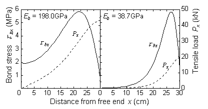
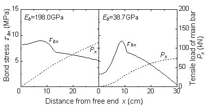
The distribution of the bond stress (solid line) and the tensile load (dotted line) according to the value of the Youngfs modulus are shown in Fig. 14 and Fig. 15 in case with and without lateral reinforcement, respectively.

Fig. 14 Distribution of the bond stress in case without lateral reinforcement

The reinforcements used are of two types, namely, steel (198GPa) and glass fiber (38.7GPa). The graphs show that, in the case of the lower Youngfs modulus, the area where bond stresses are acting is small, thus the tensile load at loaded end becomes small.
CONCLUSIONS
@
REFERENCES
@