PAGE 2
Mechanical Properties and Applications of FRCC

| [Reference] | Movies of glass water vizualization experiment--- SideÅ@/Å@ Up |
|
Fiber Reinforced Concrete (FRC) Concrete is brittle material for tensile force. Concrete structures consist of merits of steel reinforcement, which is ductile material. There is a possibility of a new type of structure if tensile capacity can be expected in cementitious composites. Fiber reinforced concrete (FRC), in which tensile ductility is expected, has been studied. |
|
|
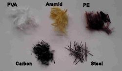
FRCC Recently, the high performance fiber-reinforced cementitious composite (SHCC, DFRCC), in which tensile ductility can be expected, has been developed. High strength organic fiber such as PVA, polyethylene fiber is mixed in mortar based materials. Though crack strain of normal concrete is several hundred micro strain, DFRCC has tensile ductility with several percent strain. |
|
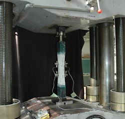
Uniaxial tension test for FRCC Currently, evaluation method for tensile ductility of FRCC is not established. "Dog-bone type" specimens are introduced to obtain reliable data under pure tensile stress. Uniaxial tensile test has been performed. |
|
|
Bending test for FRCC The uniaxial tension test is not so easy to manufacture the specimens and to perform. Bending test is also conducted to evaluate the fracture energy of FRCC. |
|
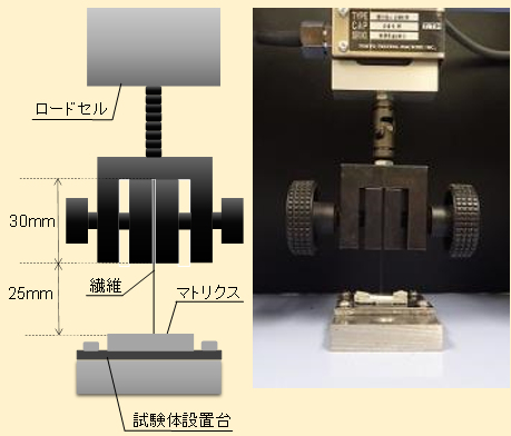
Pullout test of single fiber Tensile ductility of FRCC is controlled under the bridging performance of fiber between matrix. The bridging performance of fiber is provided by pullout characteristics of a single fiber from matrix. The pullout characteristics are influenced by bond behavior between fiber and matrix, and snubbing effect characterized by orientation angle of fiber. The fundamental pullout characteristics of fiber can be evaluated by the pullout test of single fiber. |
|
|
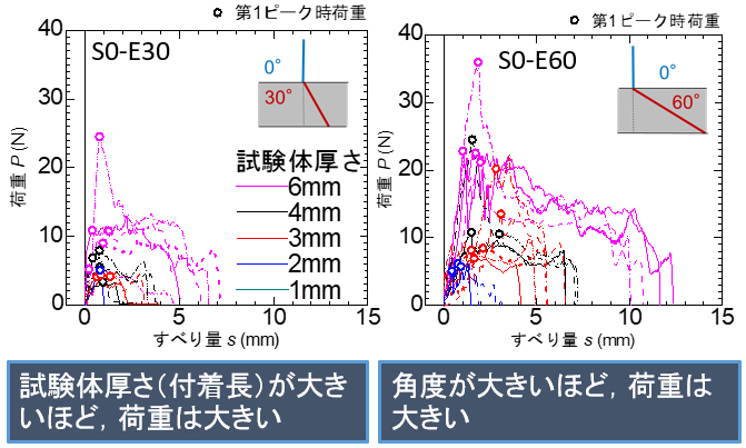
Pullout test result From the pullout test results, it is recognized that the maximum pullout load increases as the thickness of matrix (bond length) and orientation angle increases. |
|
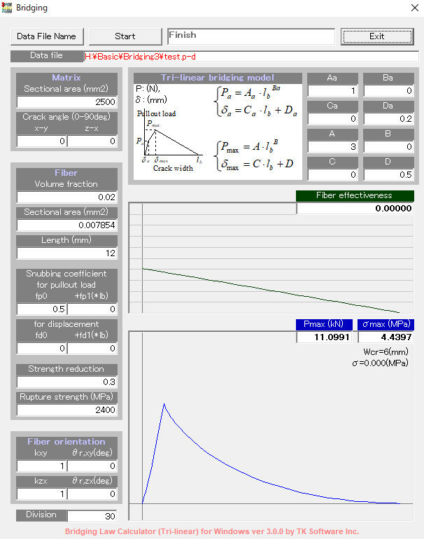
Calculation of bridging law Calculation of tensile stress vs. crack width curve (bridging law) can be performed by numerical calculation in which the pullout loads of fibers in matrix are all added up under modeling of pullout behavior. (Program for calculation of bridging law is available here.) |
|
|
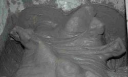
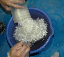
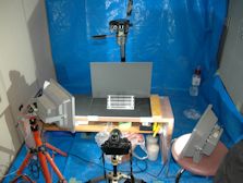
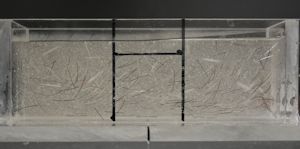
Orientation vizualization of the fibers There is a possibility to not show the expected tensile performance if the fibers do not have a orientation to be effective for the subjected force. High viscosity of mortar matrix influences the flow of the fibers. The vizualization experiment using liquid glass is performed to evaluate the fiber orientation in FRCC. |
|
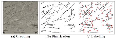
Vizualization method The sets of the coordinates of the target fibers are obtained by the image processing. The fiber orientation angle is calculated and the influence of matrix flow is investigated. In other words, we can control the fiber orientation in DFRCC. |
|
 Movies of glass water vizualization experiment SideÅ@/Å@ Up |
|
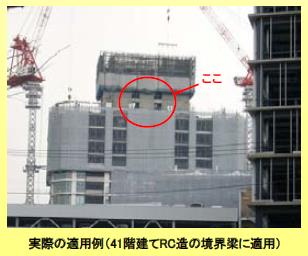
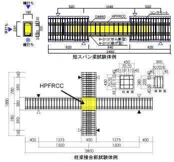
Structural application of FRCC FRCC has been applied in the coupling beams of center core systems used in high-rise RC buildings. The coupling beams are designed in compliance with the following two requirements, (1) no substantial load degradation at a translational angle as high as 4% and (2) no cracks influencing durability with a width greater than 0.3 mm after an earthquake. It is difficult for conventional RC beams to keep the crack opening under 0.3 mm after the elements have deformed at an angle of 4%. |
|
|
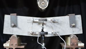
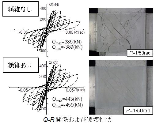
Structural experiment The matrix inside the panel zone of beam-column joint has to carry the complex and high stress. However, ordinary steel reinforcement has not so large improvement to shear capacity of panel zone and bond strength of main bars. Scale specimens such as coupling beam (upside photo) and beam-column joint (lower photo) are loaded in simulation for earthquake force. Evaluation methodology for loading capacities and deformability is discussed based on the test results. |
|
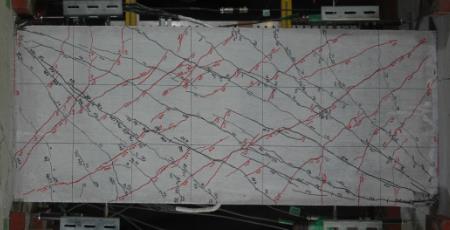
Shear test for FRCC beams The upper specimen is by ordinary concrete, and the lower specimen is by FRCC. Both specimens have same reinforcement and were subjected to same loading. The plotted lines on the specimens indicate the cracks at the loading cycle of 1/100 rad. The specimens show very different crack behaviors. Same loading cycle gives the same deformation to the specimens, the difference of the crack width is given by the number of cracks. 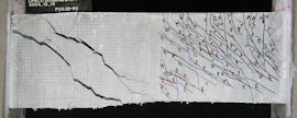 Movies of cracking of beam specimens PVA20-60L(B), PVA20-60L(A) |
|
|
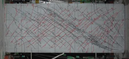
Beam-column joint test The specimen with fibers shows fine cracks and small crack spacing. The effect of fibers to cracks dispersed is recognized. The specimen without fiber shows the localization of crack opening and the decrement of the shear force. |
|
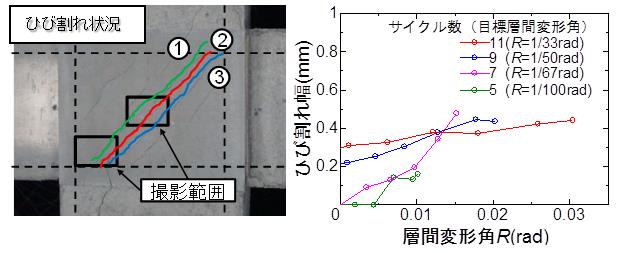
Evaluation of bridging effect of FRCC The cracks on the panel zone are taken by digital cameras, and the relationships between crack width and load, story angle are obtained. The bridging effect of fibers is evaluated using the bridging law of fibers. |
|